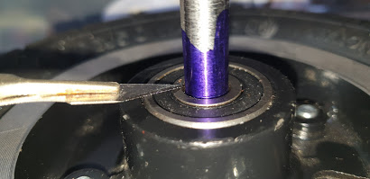
This post is quite long. Video of it in action at the end!

It's a pretty basic lathe, but it fits into the very limited space I have in my garage workshop. Recently I needed to use power feed on the lead screw, which is when I realised it could do with a modern upgrade.
As with most low tech lathes, the lead screw is driven from the spindle via a set of gears, and by changing these the feed speed can be set. On my lathe the gears are proper 1940s metal things, and the gear assembly involves interlocking them with pins and adjusting two mounts that can be swivelled to allow for the differing diameters.


There is no motor speed controller and having to change the gears every time a new feed speed is required is a real pain. So I decided to try adding a stepper motor with adjustable speed. By having this drive the lead screw handle I could still operate it by hand when the stepper was disabled.
I've recently fitted some cheap LCD DROs to the carriage, cross slide and tail stock quill. It occurred to me that combining the stepper motor feed with positional information from the carriage might be useful.
There is too much slop on this old lathe for a full CNC conversion, and replacing the lead screw with a ball screw was something I didn't want to do.
The idea was to have the following features in a 'Leadscrew Buddy'
- Variable speed powered lead screw. Forwards and reverse.
- Display the carriage position indicated by the DRO sensor.
- Allow the displayed position to be zeroed.
- With a home point set, allow a full speed return to the home position when selected by the operator. The home position is not accurately sought. It just moves as fast as possible until it has gone past the home position. This will speed up the homing process.
- Implement a seek mode. After a zero point and destination point are set, the carriage will seek the destination point at the set speed. Upon reaching the destination point, the carriage will stop. The operator can then request the carriage to be homed at full speed, and the process repeated.
Is this the most sensible way to control a lathe carriage?...probably not, but I just wanted to see if could be done.......
First thing was to see if I could read data from the LCD sensor. The sensor is synchronous, one way serial communications with the sensor generating the clock pulses. There are Arduino libraries to read these in existence, but being from a PIC world I thought this would be a good opportunity to learn how the Arduino manages edge interrupts.
So I lashed up a test jig on a breadboard. Initially I got nothing, but checking the output from the sensor showed a voltage too low to trigger the Arduino detection circuitry, so I bunged a couple of NPN transistors with some pull ups and that sorted it out.
Here you can see the difference before and after the signal is amplified:

With the interrupts in place this article was most helpful. I used a serial 16x2 LCD display (which I did use a library for) and it wasn't long until my display was matching that of the display supplied with the sensor.

Next was to make a test jig for a stepper motor. I had a spare Nema 17 so I designed a set up to connect the stepper and sensor to a M6 threaded rod and 3D printed it in ABS. This way I could prove the concept before modifying the lathe and spending money.
I added a shaft couple to the design using this excellent parametric SCAD model by Revar on Thingiverse.

Pretty ugly, but it allowed me to prove the concept. The biggest problem with these cheap (~$35) sensors is the slow update rate of about 10Hz. The immediate issue is that when trying to find a given position at speed, the destination position might be passed in between sensor updates.
For example, with a destination position of 10.00mm reading might come from the sensor at 9.80mm then 10.20mm. To ensure the destination position was always reached I implemented two seek strategies:
1) A calibration. First the maximum possible stepper speed is found and stored with a simple "set the speed and try it" mode. The full speed will only ever be used when returning to the home position.
With the max speed set, it's assumed that the maximum cutting speed will never be faster that 1/4 of that speed, and the slowest speed will never be less than 1/20th of the max speed. A calibration routine then runs the carriage at these two speeds and notes the maximum difference between two consecutive DRO readings at that speed. An extra 20% is added as a safety margin, and the values stored.
With the max speed set, it's assumed that the maximum cutting speed will never be faster that 1/4 of that speed, and the slowest speed will never be less than 1/20th of the max speed. A calibration routine then runs the carriage at these two speeds and notes the maximum difference between two consecutive DRO readings at that speed. An extra 20% is added as a safety margin, and the values stored.
A simple linear equation solver is then used to estimate the maximum expected position difference given a particular speed.
2) The stepper is driven by a timer interrupt whose rate is set according to the required speed. As the carriage approaches the destination position, it decelerates. When the difference between the current position and the destination is less than the delta obtained in 1), the step rate is synchronised to the DRO sensor update. So before the step pulse is sent, the current position is known.
This does mean it's quite slow for the last 0.2mm or so, but positioning to this accuracy by hand involves some pretty careful hand wheel turning. To have it done for me, repeatably, is a huge benefit.
So with the software working. Time for some hardware.....
I designed a simple PCB using DesignSpark. This is my PCB CAD package of choice ATM. I found KiCad a bit clunky and I don't like the way it manages libraries. Just my preference.

The circuit is to use a rotary encoder as the main menu navigation and speed control. I used Paul Stoffregen's Encoder library to handle all the debouncing, and wrapped this in a class to allow me to set a max/min range of values, an increment per detent, increment or wrap mode etc.
There are is selection of buttons, each connected to a nano input with programmable pull up. The DRO sensor is powered from the 3V3 pin of the Nano, so no batteries required.
The PCB is double sided, but with as many tracks as possible on the bottom copper. The top layer is implemented using tinned copper wire cut to length.

I have a DIY CNC router which I use to mill my PCBs. She is called Bertha. UK residents of a certain age will understand....it was time to fire her up.

Using the excellent FlatCAM I created tool paths for the track cutting, drilling and board cut out...
Some time ago I made some custom clamps for holding PCBs above the router bed. Using these the PCB blank was fastened and Bertha did her work.


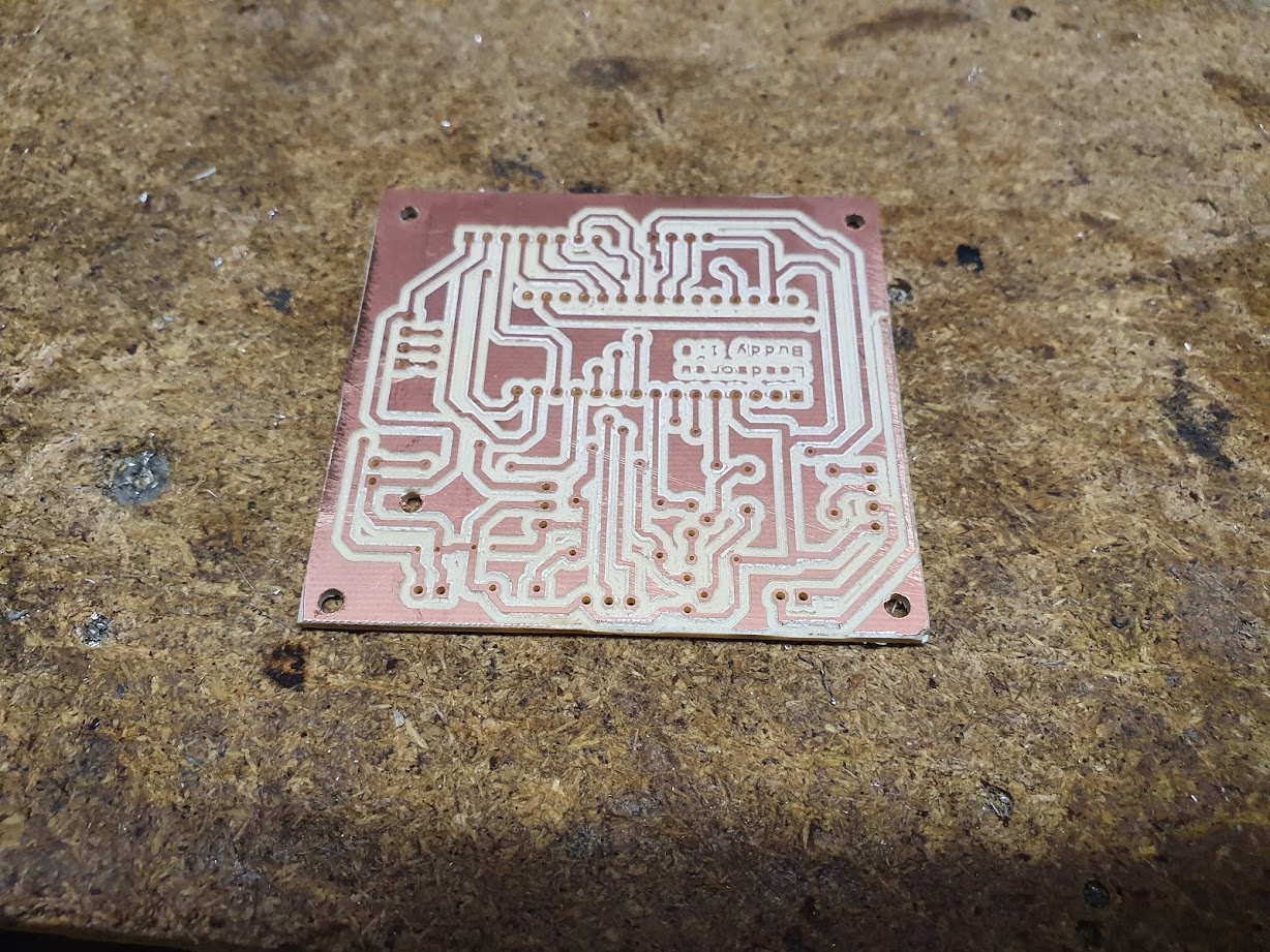
Not too bad for home made. When assembling the PCB, for the top layer I stretch tinned copper wire with pliers whilst held in the vice to make it nice and straight before cutting it to size.

When completed, I realised I'd placed a connector right in front of the Nano USB port, so I gave it a height boost with some 0.1" strips. This will only be used during software development.

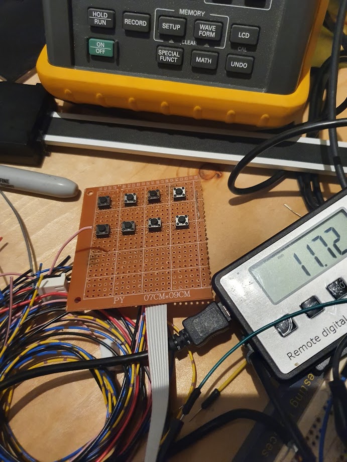
This lash up allowed me to get most of the software function implemented before I had to go near the lathe.
With the software sorta ready, the next step was a box. I dug an enclosure out that had been lying around for ages. This had an aluminium sheet as the fascia and I planned to use Bertha to cut out the holes.
Fusion 360 seemed to be gaining popularity and I thought this would be a good opportunity to learn it. My free CAD package of choice has been PTC Creo elements/direct modelling express and the jump to Fusion was so frustrating I concluded I should have started with something simpler.
Reverting back to PTC got me this:

The addition of an emergency stop button seemed sensible. I got the model for this and the LCD display from Grabcad and imported them straight into PTC.
Meshcam was used to create the tool paths. Rather than risk ruining the enclosure, some test cuts were tried on scrap MDF first. The V cutter used for the PCB track cutting was used to engrave labels for the controls.

Good job I did a test cut as I messed up the button cut outs. After a quick re-CAD a second test cut confirmed everything was OK. Time to cut the real thing.
Using a cheap single flute cutter from Amazon for the holes, it came out pretty good.

I wanted to highlight the text in black. Using a squeegee to force black acrylic into the engraved text shows up the letters really well. However, it's hard to avoid getting smears of residual paint.


The circuit board is held in place with a piece of MDF laser cut with my Chinese blue and white to fit the mounting holes in the base of the box.

To mount the LCD, some plated brass stand offs were turned down to match the height of the display module. Ironically the intended seek function of the Leadscrew Buddy would have helped here. I had to rely on the DRO and position the carriage manually.

These came out just right. They are used to allow the display to be clamped against the fascia without stressing the display PCB.

Wiring up the internals of the box went well. I use circular connectors by MulticompPro for connection to the outside world as these have a great current capacity and a threaded cowl to hold them in place.

The power supply is a 24V 10A switch mode from Amazon. I used Makercase to create a housing for it, then added some cooling and connector holes.

And back to the blue and white to cut it from MDF.


The orange corners are fasteners for the lid. They are 3D printed ABS with threaded brass inserts pushed in with a soldering iron.

Time for a test on the bench. In my enthusiasm to try it out I plugged the power supply into the wrong connector on the PCB, giving Nano pin D9 the pleasure of 24V d.c. Needless to say, the magic smoke was released.

Cursing, but unperturbed, I reached into the banggood box for another Nano. After plugging it in I noticed Windows installing a USB/UART driver but thought nothing of it. When in place though, I no longer got data from the DRO sensor.
After visually checking the connections I went back to basics with a multi meter and found there was no 3V3 coming from the Nano.
Previous nano boards from BG have used CH340G USB/serial devices as a low cost FTDI clone.

These new boards had an unmarked IC in it's place. Whatever it is it was not creating the required voltage. Strictly speaking these boards are not Arduino Nano compatible. Caveat emptor.

Time to mount the stepper......
I chose to use a Nema 34 for the drive, and needing a mount for this I returned to Fusion 360. After importing a Nema 34 model from Grabcad and some perseverance I managed to design a half decent mount.

I was impressed with the tool path generator of Fusion. Meshcam seems to lack a fast speed setting for moves in between cuts. The resulting tool path from Fusion was impressive. With a 6mm, 2 flute bit from EW Equipment Bertha did a great job.


To mount the motor to the lathe I used a piece of 10mm x 75mm steel to attach to the coolant tray of the lathe. It was cut to the correct length on the portable band saw.

I had to use one of those right angle drill adaptors to enable me to drill the holes in the confined space.


The stepper drives the lead screw handle via a timing belt and pulleys. Before the final stepper position can be found, I need to fit these.

The hand wheel is to have a pulley fitted directly to it.


Being cast, the 'shaft' of the hand wheel where the pulley is to mount does not have a particularly good finish. I mounted it on the lathe face plate to skim it.

The pulley was initially drilled to a diameter just less than the hand wheel shaft diameter.


Because of the limited space between the hand wheel and the lead screw mount, I had to turn away some of the pulley.

The same procedure was used to fit the stepper pulley.
The pulleys are held in place with grub screws. I used the 'wobbly ruler' method to approximate the centre of it. Due to the limited space on the hand wheel, I had to put the grub screws in the belt area of this pulley.

As it's a round surface, I used a small end mill to create a flat surface for spotting, before drilling and tapping.


With both pulleys fitted I could now find the right position for the stepper.


A quick test showed everything working as expected.
Next was a mount for the control panel. I planned to use a piece of steel bar welded to the motor mount plate to offset and move back the panel. I cut a piece of 25mm mild steel rod, then cut an angle onto both ends manually with the the portable band saw. The first time I've used it this way and it's a bit scary...


So I cleaned it up on the mill.


The idea is to have a vertical bar coming off this, straight up to the control box. I want to be able to adjust the angle so I made a hole for an 8mm cap head bolt to go into the vertical bar.


With the sloping bar tidied up, I was ready to weld it to the stepper mount plate.

I had the good sense to tack weld and try it before going the whole hog. Glad I did as the first try had the sloping bar catching on the timing belt. After a quick re-alignment and a second check it was permanently fixed.

A mounting plate was cut from the same material as the motor mount. Using a quickly knocked up CAD model allowed me to ensure that the control box mounting holes aligned with this plate.


I managed to bust another tap....I am tapping M4 but used a 3.2mm drill instead of the official 3.3mm. Seems small, but maybe that and my overzealous use of the ratchet tap wrench combined was enough....
That tap is stuck in. Ah well, 3 screws are not as good as four, but better than none.

The control box is at a bit of a weird angle, so a Heath Robinson jig held the plate to the rod until it was tacked in place.


Installed on the lathe it looks OK.


I found the DRO sensor was not quite level with the lathe bed, but a few adjustments with the help of an indicator dial sorted this out.


So does it work?...Yes. I'm really happy with it. The seek function is really useful when doing repeated cuts to the same position on a work piece, and the generic power feed gives a much better surface finish than I can achieve by hand.
Going forwards, I'd like to add a 'relative step advance' mode where you set a distance, and the carriage will move forwards by that amount relative to the current position when requested.
It would be interesting to replace the cheap DRO sensor with an optical one which might help with the position update speed.