Wednesday, 23 October 2013
Filastruder Build
I started building my Filastruder kit over the weekend. Stage one is to fasten the nipple (AKA pipe) to the flange.
Then slide the hopper body onto the nipple,(not shown in this pic), and fit the threaded coupling. The coupling is where the brass die screws into.
Stage three involves fitting the auger and assembling the thrust bearing. The thrust bearing is sandwiched between two washers which can be seen butted up against the thrust plate (the upper of the two plywood sheets).
The next stage is to fit the drive collar. This is a 3/8" socket which locks with a small pin against the flat on the output drive of the gearbox.
The pin is held in place with some tape.
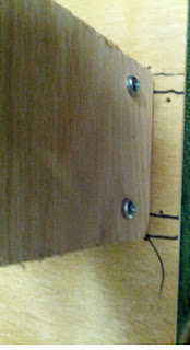
The motor is fitted to a small sheet of plywood which is fastened to the base plate with a couple of wood screws. Don't do what I did and pre-drill the screw holes so that the screws clash with the bolts holding the motor in place.
Here it is all fixed together. The heater band and electrics need to be added next.
After fitting the heater band and doing a small test extrusion, I noticed a significant temperature drop from that dialled in on the temperature controller to the actual temperature. A difference of around 30C when the drive motor is running. This is to be expected as the molten ABS is taking heat away from the heated die. I added some extra insulation in the form of aluminium foil:
Here it is with 3D printed switch/ PID controller bracket from Thingiverse and the extended hopper fitted:
The output spooled up:
I've found that the best scenario is to have it reasonably high up. I used a height of about 1.7m for this run. Also, the landing zone needs to be as clear as possible so the filament does not build up as it rubs against (say) a wall, then jars as gravity frees it. I've been getting +/-0.1mm on the filament. I believe I can improve this by reducing the aforementioned jarring. Overall: HAPPY ;O)
Subscribe to:
Post Comments (Atom)


No comments:
Post a Comment