Friday, 8 September 2017
More CNC router
Visit Tagbits to see the full range of tagger products described in this blog.
I have been continuing work on my DIY CNC router this week by starting on the Y axis. This moves along the linear rails at the top and bottom of the Y gantry:
The Y axis needs mounts top and bottom for the linear bearings, shown here in blue.
I bought some 15mm aluminium plate from Materials4me.co.uk cut to size. I was quite impressed with their price and service as the pieces arrived cut accurately. I used the print and punch technique I described here to ensure the holes I needed were accurately aligned with the holes in the bearings.
The holes aligned perfectly but, as I had simply stuck a 2D print of the centres onto the plate and then drilled, I had failed to align the holes with the edge of the plate. This is how it should be:
And this is what I ended up with:
I realised that I would be unable to accurately align the paper with the centres printed on it with the edge of the work piece. Which brought me to a complete halt. A few months ago I was fortunate to take possession of a Warco WM-16 vertical milling machine.
I fitted it with a third party digital read out for the X and Y axes. This uses optical sensors to allow me to position the bed to an accuracy of 0.005mm. By aligning the work piece parallel to the bed, and centring the mill on one of the corners I can accurately drill all the holes knowing that they will be aligned with the edge.
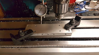
The only issue is to accurately place the work piece. To do this I clamped the piece to the bed. I then used a dial indicator to check the part alignment by winding the bed backwards and forwards. Noting the change from one end to the other and moving the piece to compensate until the dial did not move (by much) from one end to the other it is possible to get the piece edge parallel to the bed axis.
Using an edge finder I was able to align the chuck with the corner of the piece.
Here is how they work:
And with a print out annotated with dimensions from the CAD system, using the digital read out I was able to drill each hole with fantastic accuracy.
Here is the Y axis half assembled.
In conclusion, the print and punch method I have used previously is great for aligning holes unless their position needs to be relative to some other edge.
Subscribe to:
Post Comments (Atom)


No comments:
Post a Comment