I've started making an EV to take to EMF camp 2024. It's going to be driven by snowmobile\ATV tracks which I got from AliExpress.
 |
| Snowmobile/ATV tracks |
The track units are driven by a splined shaft. As this is a custom build I was going to have to make this for myself.
 |
| Gonna need splines for this. |
My plan was to use a HV6 rotary table on the mill and dividing plates. This is a machine chuck mounted onto a rotating table. By turning a handle with a 90:1 reduction ratio the chuck angle can be accurately controlled. Dividing plates are used to allow number of positions to be defined such that the chuck can be configure to perform a 360 degree rotation in (say) 23 stages. i.e. 360/23 degrees per stage. At each stage a single spline would be cut.
 |
| Rotary table set horizontally with dividing plates. |
The rotary table would be mounted horizontally on the milling machine and a slitting saw run horizontally to cut each spline.
Reading the HV6 manual it occurred to me that the dividing plates might not work out for me as they involve counting full and partial rotations. This is the sort of thing a microcontroller would be great at and is quite similar to the Leadscrew Buddy I created for my lathe.
I designed a simple circuit to use a RP2040 to drive a stepper motor with a LCD display, a few buttons and a rotary encoder for user input. I chose a MakerNano RP2040 board as it is fully supported by the Arduino IDE and was less than £10 at the time of writing. It's also 32bit. Although using integers the numbers in the software will be quite large so something more powerful than an Arduino Nano seemed appropriate.
 |
| Simple RP2040 circuit. |
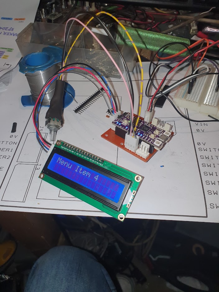 |
| Working on the encoder driven menu system |
And using Design Spark for the schematic allowed me to quickly create a PCB....
 |
| PCB designed with Design Spark |
Which I milled on my CNC router: Bertha
 |
| Bertha at work. |
PCB came out OK.
 |
| Post milling PCB |
The software allows the rotary table handle turns per revolution (defaults to 90 which is pretty standard) and the stepper motor micro steps per revolution to be set by the user. These are then stored in EEPROM. The user simply dials in the number of splines required and the software calculates the number of steps per spline. Next/Previous controls allow the table to move when the current spline has been cut and the LCD displays the current spline number and total spline count.
With a table reduction ratio of 90:1 and 1000 steps/revolution micro stepping there are 90 x 1000 steps per table revolution. 0.004 degrees per step. That should be enough (and the 32bit CPU won't break a sweat).
I also designed a 3D printed case and CNC routed fascia.
 |
| The box |
The fascia was cut from aluminium and v carved with control labels. I squeegeed in black acrylic paint:
 |
| Acrylic paint after squeegee |
Allowing the excess to dry a paste of sodium bicarbonate easily cleans the surface. With a light spray of clear varnish as a sealant it looked pretty good with the controls fitted.
 |
| Not bad for home made... |
I'm using a stepper driver that I had lying around. Of the two I had this one alone worked. The other driver indicated 5V was required at the inputs and the RP2040 runs at 3V3. The working driver didn't mention 5V anywhere.
With the box printed the parts were fitted and wired. I'm using 24V dc power and the 5V linear regulator on my PCB would get too hot at this voltage. I added a small switching regulator board from AliExpress to drop this to a more reasonable 9V feed into the PCB.
 |
| Everything fitted. |
With the fascia and controls fitted it's looking OK.

To connect the stepper motor to the rotary table I used the HV6 stepper adaptor mount by Bitesizedmoose on Thingverse. I wasn't happy with the shaft coupler in this design so I took the parametric shaft coupler by Revar and tweaked the OpenScad script to match what I wanted.
There are 23 x 60 degree spines required on the shaft. I ordered an appropriate V groove cutter from AliExpress:
 |
| 60 degree V groove cutter |
I dialled in the required 23 splines and had a trial run on Delrin.
 |
| Test piece looks good |
This turned out so well I decided to try the actual drive shaft. I'd bought a suitable piece of steel bar from Noggin End Metals and had already put some time into it on the lathe getting it prepared.
With it installed on the mill each spline took about 10 minutes to complete as my small machine can't handle deep cuts.
 |
| Cutting the splines |
After each spline pressing the Next button moves the workpiece into the new position.
Did it work. Well, the proof of the pudding is in the eating..........
No comments:
Post a Comment