Saturday, 15 February 2014
More rolling my own..part 2
I've had some great results with my Filastruder and ABS pellets from CraigRK
The temperature and nozzle diameter are critical. With the standard nozzle supplied by Filastruder I got filament I was not happy with. It was brittle when extruded at 220C, and had a rough outer texture. Anything much below this suffered from too much die swell and I was getting filament of 3.2MM which jammed one of my extruders. I found this was the case with pellets from several sources, so this is obviously a result of the hardware.
Lower temperatures seemed to improve the filament quality, but there was a corresponding increase the die swell. I'm now running with a 2.5mm orifice on a filtered die. This was supplied at 1.75mm and drilled to 2.5mm, and with an extrusion temp. of 190C.
I found horizontal extrusion less than satisfactory with jams regularly occurring. I tried vertical extrusion but found that the hopper guides available on Thingiverse simply jammed after a few minutes extrusion.
So I got a hack saw to the vertical hopper feed, and hot aired the chute until I could screw in a cola bottle, and mounted the filastruder at 45 degrees:
This gave me reliable pellet feed and after a nights worth of extrusion I was presented with this:
About 0.8Kg of filament. It is of really good quality. Here is a 10x view under the microscope:
Nice and smooth. And it is not brittle. It turns white as it is bent around a small radius as you would expect HQ filament to do.
Here is one of my Lasertag parts printed wholly from home grown filament:
I'm now at the stage where my primary source of filament is myself. It's much cheaper! The only problem I have now is spooling it up, perhaps I should get a Filawinder.
Thursday, 16 January 2014
Milestag UMT audio
Visit Tagbits to see the full range of tagger products described in this blog.
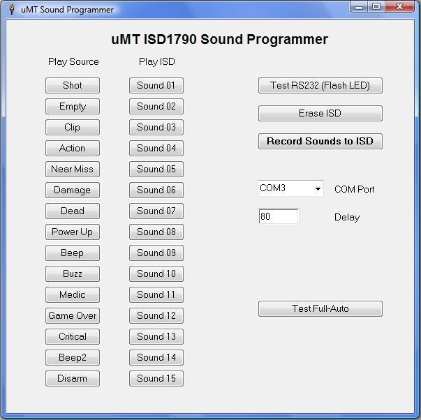
I'm being asked to do several Milestag projects that use my Tagbits UMT boards, but they need audio resources that are not supported by the standard UMT audio tool.
Jim at Lasertagparts kindly supplies his sample programming utility and audio samples without licence.
However, it only supports 15 sounds, and none are allowed to be longer than the standard samples that Jim provides.
I did a project that shoehorned alternative samples into the lengths available here. But it was a pain.
So I finally got around to writing a utility that allows me to point the PC at a directory with some .WAV files in it.
It reads them all in and works out the lengths, then allocates these to 'sectors' within the ISD1790 playback chip.
This device has analogue memory, with each sector having a timespan of 0.125 seconds.
My program loads the samples up, allocates them sectors, programs them into the the UMT board ISD1790 (combined with custom PIC software to do this), plays the sample from the PC, plays the sample from the UMT board and finally generates a 'C' structure with all the correct addresses in.
Here is a screenshot of the program:
And here is the 'C' output it produces:
typedef enum
{
e01_shot_umt,
e02_empty_umt,
e03_clip_umt,
e04_action_umt,
e05_miss_umt,
e06_hit_umt,
e07_kill_umt,
e08_power_umt,
e09_beep_umt,
e10_buzz_umt,
e11_medic_umt,
e12_gameover_umt,
e13_critical_umt,
e14_beep2_umt,
e15_disarm_umt,
} ESoundId;
#define LOWBYTE(value) (value & 0xff)
#define HIGHBYTE(value) (value / 0x100)
typedef struct
{
byte byStartLowByte;
byte byStartHighByte;
byte byEndLowByte;
byte byEndHighByte;
}SSound;
SSound sounds[] =
{
{LOWBYTE(0x0010),HIGHBYTE(0x0010),LOWBYTE(0x0018),HIGHBYTE(0x0018),},
{LOWBYTE(0x0019),HIGHBYTE(0x0019),LOWBYTE(0x001A),HIGHBYTE(0x001A),},
{LOWBYTE(0x001B),HIGHBYTE(0x001B),LOWBYTE(0x001D),HIGHBYTE(0x001D),},
{LOWBYTE(0x001E),HIGHBYTE(0x001E),LOWBYTE(0x0023),HIGHBYTE(0x0023),},
{LOWBYTE(0x0024),HIGHBYTE(0x0024),LOWBYTE(0x002A),HIGHBYTE(0x002A),},
{LOWBYTE(0x002B),HIGHBYTE(0x002B),LOWBYTE(0x002F),HIGHBYTE(0x002F),},
{LOWBYTE(0x0030),HIGHBYTE(0x0030),LOWBYTE(0x003D),HIGHBYTE(0x003D),},
{LOWBYTE(0x003E),HIGHBYTE(0x003E),LOWBYTE(0x0048),HIGHBYTE(0x0048),},
{LOWBYTE(0x0049),HIGHBYTE(0x0049),LOWBYTE(0x004C),HIGHBYTE(0x004C),},
{LOWBYTE(0x004D),HIGHBYTE(0x004D),LOWBYTE(0x004F),HIGHBYTE(0x004F),},
{LOWBYTE(0x0050),HIGHBYTE(0x0050),LOWBYTE(0x0056),HIGHBYTE(0x0056),},
{LOWBYTE(0x0057),HIGHBYTE(0x0057),LOWBYTE(0x005F),HIGHBYTE(0x005F),},
{LOWBYTE(0x0060),HIGHBYTE(0x0060),LOWBYTE(0x0063),HIGHBYTE(0x0063),},
{LOWBYTE(0x0064),HIGHBYTE(0x0064),LOWBYTE(0x0067),HIGHBYTE(0x0067),},
{LOWBYTE(0x0068),HIGHBYTE(0x0068),LOWBYTE(0x006D),HIGHBYTE(0x006D),},
};
It will not work with Jim's standard Milestag UMT software, and I initially thought it could be patched into the existing Milestag code by putting in the new ISD addresses, however, a quick look at a disassembly of Jim's code shows that this will not be possible. However, it could easily be used with my open source UMT code on Github.
Sunday, 12 January 2014
Revised router design
Having finished my router design. I posted some pictures in the forums at http://www.mycncuk.com/, asking for comments. A few of the guys there suggested that my design was potentially weak in that the Y axis SBR20 bearings were loaded incorrectly.
I've had a re-design of the Y gantry. This is now formed from 3 pieces of 15mm aluminium plate bolted together. This depth of 45mm is exactly enough to allow me to mount the Y SBR20 rails on the top and the bottom of this section. Also, I've changed the Y stage to be a rectangular box that surrounds the Y gantry, with the ballnut on one side, and the Z axis on the other.
Thursday, 2 January 2014
Post Xmas Toy
Visit Tagbits to see the full range of tagger products described in this blog.
I've been using my reprap printers to make Milestag Lasertag gun bodies for some time now. But I believe I can make even better gun bodies when removing material, rather than adding it.
So I've designed a CNC router,it's a moving bed design.:
It is designed around some 45mm extruded aluminium that was being thrown out at work. I'm using 20mm (SBR20) linear bearings throughout so it should be pretty tough.
I received the all the linear bits today from Chai at LinearmotionBearings. As my design is a custom build, he made me up an order to my requirements which arrived today, about 14 days after the order, and well packaged:
Everything was there. The ball screws are beautifully machined, but may need a going over with emery cloth when fitting the brackets.
I'd deliberately delayed committing myself to buying any additional parts until these turned up. And I was right to do so. Of the 3 custom linear rail lengths I had requested, two were +5mm in length. This means that I now need to buy custom 45mm aluminium extrusions, rather than the ones I had.
This isn't a major problem, but it has added about 30UKP to the cost of the machine.
Thursday, 19 December 2013
Illuminati
Visit Tagbits to see the full range of tagger products described in this blog.
My Mendel90 lives in a heated chamber in the garage. It's dark in there, and I got fed up of checking on print progress with a torch.
Luckily I work for a company that has this sort of thing lying around:
It's a PCB strip with 5 RGB LEDs wired to produce white when supplied with 12V d.c. This was a Mk1 which was to be binned, so I saved it an fitted it into my M90 heated chamber.
Now I can see the prints as they progress:
Further Filastruder Prints
Visit Tagbits to see the full range of tagger products described in this blog.
I made some black ABS filament using some masterbatch from CraigRK. It came out really well and I am happy with the prints I have from it. Both on my Mendel90 and gunbot:
One thing I have noticed is that the filament quality from the filastruder is better when the temperature is lower. However, with a low extrusion temp. the die swell is so much with the standard 3mm nozzle that I was getting filament of 3.2mm in diameter. This proved a problem for gunbot.
Due to the metal shards I was getting in the filament (which has cleared now BTW. See the comments in the link) I ordered a nozzle with inbuilt filter.
Quite by accident, they sent me a 1.75mm nozzle instead of the 3mm one I ordered. They said I could easily fix this by drilling out the hole to 2.7mm, as is drilled for the standard 3mm nozzle. I decided to start small, and started with 2.5mm.
Extruding at 185C with this nozzle gave excellent results. 3mm bang on and super smooth filament with the plastic pellets from CraigRK.
Saturday, 30 November 2013
Gunbot Broken
I've had my custom 250mm x 150mm 3D printer 'gunbot' for about 2 years now...and I've broke it. It uses the extruder controller that nophead developed some time ago and I went and plugged the extruder stepper motor where the hot end and thermistor should be connected. This connected 12V to the input of a 3.3V micro, and it is no more.....
The micro in this design is a 28 pin TSSOP package and this is a bit hard to remove without resorting to scalpels.
But my mate Dave has access to 22,000UKP worth of SMD rework station. It's a nice piece of kit that heats the PCB from underneath and when near the re-flow temp, activates an infra red source to heat the targeted chip to the melting point of the solder. Here the IR beam can be seen targeting the faulty chip:
After the faulty chip is removed, a CCTV camera with a zoom lens is used to accurately apply solder paste to the pads:
The SMD rework machine has a CCTV camera and a prism to allow the chip and the PCB pads to be aligned. A light source can be faded upwards or downwards to illuminate the PCB or the underside of the chip to be placed. By fading between the chip and the PCB pads the chip can be accurately aligned. A vacuum holds the chip on a manipulator, and the chip is lowered onto the pads, and the vacuum released to free the chip.
Here is the PCB with the replaced MPU:
The micro in this design is a 28 pin TSSOP package and this is a bit hard to remove without resorting to scalpels.
But my mate Dave has access to 22,000UKP worth of SMD rework station. It's a nice piece of kit that heats the PCB from underneath and when near the re-flow temp, activates an infra red source to heat the targeted chip to the melting point of the solder. Here the IR beam can be seen targeting the faulty chip:
After the faulty chip is removed, a CCTV camera with a zoom lens is used to accurately apply solder paste to the pads:
The SMD rework machine has a CCTV camera and a prism to allow the chip and the PCB pads to be aligned. A light source can be faded upwards or downwards to illuminate the PCB or the underside of the chip to be placed. By fading between the chip and the PCB pads the chip can be accurately aligned. A vacuum holds the chip on a manipulator, and the chip is lowered onto the pads, and the vacuum released to free the chip.
Here is the PCB with the replaced MPU:
Subscribe to:
Posts (Atom)