Tuesday 3 October 2017

CNC Router Completed


To finish my router I needed to make the Z axis. Here you can see the linear bearings and the ball nut mount on top, with the Kress router mount below. I had already ordered some 15mm plate aluminium for this and using the print and punch method I centered the holes.
The linear rails that guide the Z axis needed fitting to the Z axis mount plate that rides on the Y axis. I followed my usual print/punch technique but fortunately I placed the linear rails that had had drilled over the print, and noticed that only the first 4 holes at each end lined up with the print. I had asked someone to drill the holes in the linear rails for me and I have no idea how this happened. So I have 4 holes that are aligned at the top of the rails, with another 8 holes below that are not. To get around this I drilled and tapped the 4 top holes of each rail that were OK, then I fitted the linear rails and bolted them down. I then fitted the Z axis onto the rails and moved this up and down to make sure the rails were parallel. I then centered the existing holes at the bottom of the rails in the vertical mill, and drilled the Z mount plate.
These holes were then tapped and the Z rails fitted again. With the Z rails held in place to and bottom AND aligned with the linear bearings, I centered, drilled and tapped the remaining holes. Whilst tapping the linear rail mount holes, I realised that some of the bolt holes that fasten the Z mount plate to the Y axis needed to be recessed as the rails were directly over the holes and these needed to be flush to the surface. To allow easy alignment of all the holes I milled a slot and a counter bore slot at these positions to allow an M6 cap head bolt to be recessed. You can see these here whilst I tap the linear rail holes.
Here is the Z mount plate after milling, tapping and drilling.
After assmbly, I fitted the Kress router and wired up the stepper motors and limit switches to check the fit. The stepper motors connect to the ball screws using a plum joint to ensure any miss alignment between the motor shaft and the ball screw does not cause a problem (The aluminium cylinder with the red bit).
The motors are held in place with 4 lengths of aluminium tube bolted with a carriage bolt from Wilko.
These came from a odd length of aluminium tube I bought at a traction engine rally. They were cut to length on the lathe. The screws are coach bolts.
The head is too large a diameter and so I turned them down on the lathe.
Once in place. They provide an excellent mount for the motors. With everything I place I tested the axes only to be met with a horrible noise when the Z axis moved. Checking everything revealed nothing so I resorted to a complete disassembly. I discovered that the Z ball screw and ball nut had corroded. These have been lying around the garage for 2 or 3 years but there is no damp. The other 2 nuts/screws are ok so I think I just got unlucky. I ordered a replacement.
With the machine built, it was my plan to have it mill holes in its own bed so I could tap these and use them to fasten clamps. I have been using the excellent Mach3 as a controller for the machine. After a few false stars with this I had unsuccessfully milled a couple of 0.2mm deep holes when I realised it would be quicker to just drill the holes myself. At this stage I told the machine to home itself. When I designed the machine I was hoping that it would be capable of milling aluminium. My hopes were confirmed when I told it to home when it was 5mm deep in the bed. Mach3 homes first on X/Y then Z. As a result, I milled a 6mm wide, 5mm deep slot in the bed in 3 seconds.
During the abortive self milling attempt I realised that the bed was not orthogonal the the Y and Z axes. To fix this I asked the machine to mill itself flat,
This was a long operation.The bed is 600 x 350mm and I needed to take about 0.8mm off in 0.2mm steps using a 6mm end mill. So a day later the bed is level and I star to drill the holes for the clamps on my vertical mill.
With all the holes cut I tapped them to fit the clamping kit I have for the mill.
These are great for fastening variable height work pieces.
With everything in place. I attempted my first milling operation.

I'm using MACH3 on a an old Windows XP machine I blagged from work with a Chinese stepper motor driver and power supply driven from the serial port. It was at this point I realised the X axis was inverted. A simple checkbox change in the MACH3 application to sort it out.

Friday 8 September 2017

More CNC router


Visit Tagbits to see the full range of tagger products described in this blog.

I have been continuing work on my DIY CNC router this week by starting on the Y axis. This moves along the linear rails at the top and bottom of the Y gantry:


The Y axis needs mounts top and bottom for the linear bearings, shown here in blue.


I bought some 15mm aluminium plate from Materials4me.co.uk cut to size. I was quite impressed with their price and service as the pieces arrived cut accurately. I used the print and punch technique I described here to ensure the holes I needed were accurately aligned with the holes in the bearings.


The holes aligned perfectly but, as I had simply stuck a 2D print of the centres onto the plate and then drilled, I had failed to align the holes with the edge of the plate. This is how it should be:


And this is what I ended up with:


I realised that I would be unable to accurately align the paper with the centres printed on it with the edge of the work piece. Which brought me to a complete halt. A few months ago I was fortunate to take possession of a Warco WM-16 vertical milling machine.


I fitted it with a third party digital read out for the X and Y axes. This uses optical sensors to allow me to position the bed to an accuracy of 0.005mm. By aligning the work piece parallel to the bed, and centring the mill on one of the corners I can accurately drill all the holes knowing that they will be aligned with the edge.


The only issue is to accurately place the work piece. To do this I clamped the piece to the bed. I then used a dial indicator to check the part alignment by winding the bed backwards and forwards. Noting the change from one end to the other and moving the piece to compensate until the dial did not move (by much) from one end to the other it is possible to get the piece edge parallel to the bed axis.

Using an edge finder I was able to align the chuck with the corner of the piece.

Here is how they work:

And with a print out annotated with dimensions from the CAD system, using the digital read out I was able to drill each hole with fantastic accuracy.


Here is the Y axis half assembled.


In conclusion, the print and punch method I have used previously is great for aligning holes unless their position needs to be relative to some other edge.

Wednesday 7 June 2017

Casting PCBs in acrylic


Visit Tagbits to see the full range of tagger products described in this blog.

I've been trying to optimise the way I make Milestag sensor domes. Previously I have thermo formed acrylic sheet but this is very labour intensive. The acrylic sheet needs to be cut to size, heated in the oven, force formed, cut and sanded.

In an attempt to reduce effort, I investigated using acrylic resin to encapsulate the sensor PCBs. Initially I tried dental alginate as a moulding agent. Using the formers my neighbour made (see link) I made some moulds. These appeared to be OK until I tried casting acrylic resin into them. The alginate when set and flexible has too high a water content and this interferes with the resin curing process. Simply leaving the alginate mould longer to dry makes it become hard and dimensionally unusable.

I then tried silicone mould making kit from amazon. First I laser cut a box using Makercase that was large enough to hold the formers.


I glued this together with a hot melt glue gun. This ensures the moulding material does not leak out when it is poured.


The silicone kit comes with a white base and a pink hardener. This makes it easy to ensure it is mixed correctly. I use the larger part of a Muller corner yoghurt to mix in as the triangular shape makes an excellent pourer.


Initially I poured a 5mm layer of silicone into the box. This forms the bottom layer of the mould.


I then placed two formers onto this layer, and filled with silicone.


After the silicone had cured (about 12 hours) the box was broken away. I cut the mould in two and 3D printed a mounting jig to hold the sensor PCBs in place. I also drilled a hole in the side of the mould to allow the sensor cable to exit. This was smaller than the actual cable to prevent the resin from leaking.

After pouring in the acrylic resin I left it to cure for 12 hours.
The parts are easily removed from the flexible silicone mould. The acrylic seems to not fully cure at the interface to the mould, leaving a cloudy finish. However, a few tens of minutes exposed to the air and it clears nicely.

Friday 6 January 2017

CNC...Continued


It's been a while since I last got chance to blog my CNC router. Last post was in 2014.....so.

I've got quite a lot done since my last post. My neighbour kindly machined the Y axis risers and Y axis gantry for me. I really did not do much on these myself, so here is a pic of them after installation. You can see the linear bearings installed on the rails at the top left and the bottom centre of the Y gantry labelled 'FRONT'


This week I'm working on the Y axis itself. This will slide from left to right along the rails in the picture above.
The first plate I need to machine is coloured green in this picture from the CAD system:


So starting with a bare piece of 15mm aluminium plate:


I printed out a 1:1 plot of the hole centres from my CAD system. Using 3M spray mount, I glued this to the plate:


In engineering, a centre punch is used to mark the centre of a hole that is to be drilled. The centre punch is simply a hardened steel rod with a tapered tip. The difficult part is aligning the tip of the punch with the centre of the hole to be marked. It's easier if you use an optical centre punch. These are available for a few 10s of pounds and allow punch alignment to be accurate to within 100ths of a millimeter.

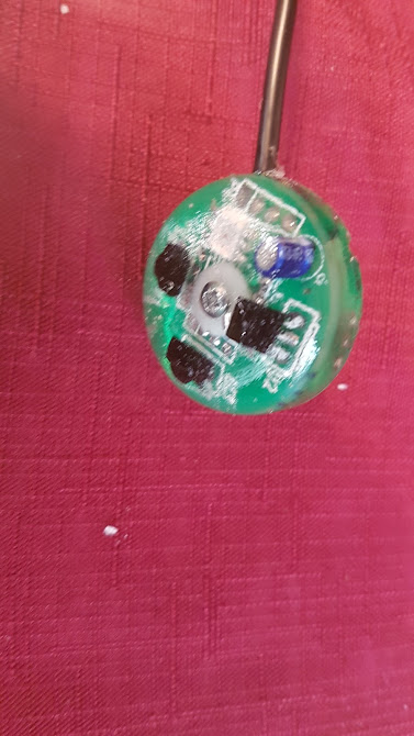
They comprise of from left to right; an alignment cone, a punch and an optical sight:


First the alignment cone is placed of over the 2D plot of the hole to be centered. On the paper stuck to the plate, this has an image of cross hairs centred on the hole to be drilled. The alignment cone of the punch is placed over this, and the optical sight fitted:

Using the magnifying properties of the sight, the alignment cone is positioned so the sight cross hair align with the markings on the paper.:


When aligned, the optical sight is removed and replaced with a metal punch.


The punch is then lightly struck whilst holding the alignment cone firmly in place. I find a pein hammer is best for this as it is light.

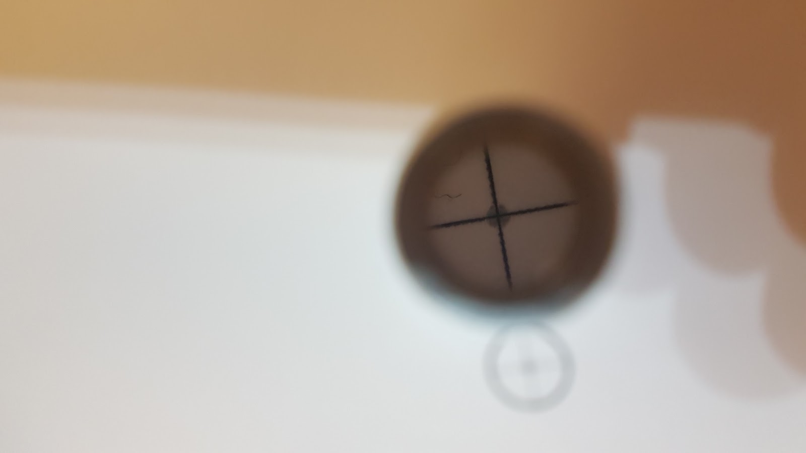
After striking with the hammer, the accuracy of the punch is obvious when viewed throught the optical sight:


When all the holes have been punched. I use a spotting drill to reinforce the indentation before drilling. This means that when I actually drill the hole, the drill bit will find its centre more readily. A spotting drill has a 90degree cutting face as opposed to the 60degree cutting face of a normal drill. Here the 3mm spotting drill at the bottom has a noticeably sharper point than its counterpart.


After running the spotting drill over all the holes, it's time to start drilling:


First I started all the holes with a 3mm high speed steel drill.


I'm initially drilling 10mm holes that will be used to attach the ball nut mount of the Y axis. I'll detail the terminlogy in another post. Basically, 4 x 10mm holes are required. After the 3mm drill, I progressed to 6mm and finally to 10mm drills.

I'm using Dormer drills here.These are made in England and are the best price/peformance ratio money can buy.


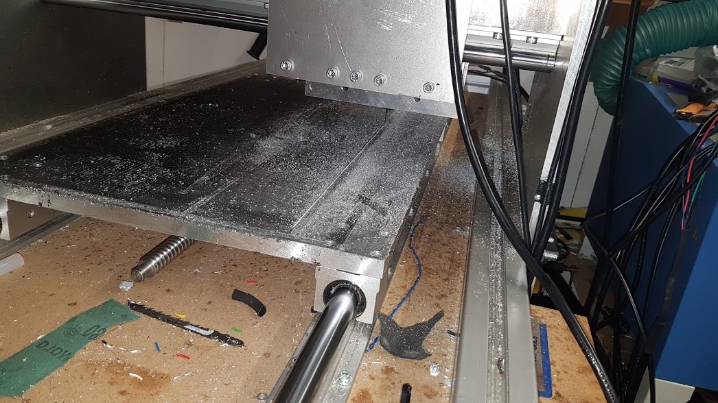
After drilling the holes for the ballnut mount, I had a dry run fitting. The bolts I am using are socket head countersunk and so really need a countersunk hole to fit in. But this shot shows all the holes aligned as desired.


Here is the ball nut mount on the opposite side of the plate with a ball screw fitted,not the acutal one to be used though.


I countersunk the 10mm holes to fit the socket head countersunk bolts:


Though not essential, the bolts look better when countersunk.