Friday, 6 January 2017
CNC...Continued
It's been a while since I last got chance to blog my CNC router. Last post was in 2014.....so.
I've got quite a lot done since my last post. My neighbour kindly machined the Y axis risers and Y axis gantry for me. I really did not do much on these myself, so here is a pic of them after installation. You can see the linear bearings installed on the rails at the top left and the bottom centre of the Y gantry labelled 'FRONT'
This week I'm working on the Y axis itself. This will slide from left to right along the rails in the picture above.
The first plate I need to machine is coloured green in this picture from the CAD system:
So starting with a bare piece of 15mm aluminium plate:
I printed out a 1:1 plot of the hole centres from my CAD system. Using 3M spray mount, I glued this to the plate:
In engineering, a centre punch is used to mark the centre of a hole that is to be drilled. The centre punch is simply a hardened steel rod with a tapered tip. The difficult part is aligning the tip of the punch with the centre of the hole to be marked. It's easier if you use an optical centre punch. These are available for a few 10s of pounds and allow punch alignment to be accurate to within 100ths of a millimeter.
They comprise of from left to right; an alignment cone, a punch and an optical sight:
First the alignment cone is placed of over the 2D plot of the hole to be centered. On the paper stuck to the plate, this has an image of cross hairs centred on the hole to be drilled. The alignment cone of the punch is placed over this, and the optical sight fitted:
Using the magnifying properties of the sight, the alignment cone is positioned so the sight cross hair align with the markings on the paper.:
When aligned, the optical sight is removed and replaced with a metal punch.
The punch is then lightly struck whilst holding the alignment cone firmly in place. I find a pein hammer is best for this as it is light.
After striking with the hammer, the accuracy of the punch is obvious when viewed throught the optical sight:
When all the holes have been punched. I use a spotting drill to reinforce the indentation before drilling. This means that when I actually drill the hole, the drill bit will find its centre more readily. A spotting drill has a 90degree cutting face as opposed to the 60degree cutting face of a normal drill. Here the 3mm spotting drill at the bottom has a noticeably sharper point than its counterpart.
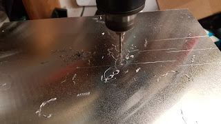
After running the spotting drill over all the holes, it's time to start drilling:
First I started all the holes with a 3mm high speed steel drill.
I'm initially drilling 10mm holes that will be used to attach the ball nut mount of the Y axis. I'll detail the terminlogy in another post. Basically, 4 x 10mm holes are required. After the 3mm drill, I progressed to 6mm and finally to 10mm drills.
I'm using Dormer drills here.These are made in England and are the best price/peformance ratio money can buy.
After drilling the holes for the ballnut mount, I had a dry run fitting. The bolts I am using are socket head countersunk and so really need a countersunk hole to fit in. But this shot shows all the holes aligned as desired.
Here is the ball nut mount on the opposite side of the plate with a ball screw fitted,not the acutal one to be used though.
I countersunk the 10mm holes to fit the socket head countersunk bolts:
Though not essential, the bolts look better when countersunk.
Subscribe to:
Comments (Atom)


