Friday, 28 September 2018

EMF Camp 2018


After my first visit to Electromagnetic Field Camp in 2016 I've been eagerly awaiting it's return in 2018. EMF Camp is a long weekend camping festival dedicated to technology and the arts, with workshops, talks, activities and demonstrations for the technically minded.
This year's event was held at one of the fields of Eastnor Castle. about 2 1/2 hours drive from where I am. This year I volunteered to run a laser tag events for 5, one hour sessions over the weekend using the 3D printed lasertag guns I've documented over the years on this blog.

To properly stage such an event I needed some inflatable barriers. These are readily available from China but I didn't want to spend any cash. Fortunately my good friend Steve Bull at Operation Lasertag was able to lend me about £2000 worth of them for the weekend. Thanks Steve!

We arrived at around 11am on the Friday.

And once through security (They were a professional event security company. They looked really bored. I asked them if this was the easiest gig they had ever done: "We've had more disruptive people at other events.....") we were in to set up the tent. Matthew had a great time bashing the tent pegs.


The event is laid out as a series of marquees in which talks, up to an hour in length, are regularly held. The marquees vary in size and an online system of talk interest registration allows the organisers to allocate the largest tents to the most popular talks.


EMF camp has been compared by some to the UK version of Burning Man. However this is a link they shy away from. EMF camp is a much more educational event with the majority of activities aimed at learning something, be it a workshop or a talk. Also, children are somewhat rare at BM, where at EMF camp they go from babes in arms upwards.

As a result of this demographic, the lasertag was most definitely busy. With English speaking parents turning up with their native Belgian or Dutch speaking kids to translate my safety briefings. It really was enjoyable, though somewhat tiring. Also, as a result of the set up and tear down times I did not get to attend as many talks as I would have liked. Nevertheless, it was great.


Andy brought along a 3D camera so we could record one of the games.


Visit Tagbits to see the full range of tagger products described in this blog.


I had some welcome help from Joshua, Keiran, Andy and Carter to run these events. It was agreed that whoever was running the event should wear the 'Stahlhelm' with goggles to indicate them as the administrator. Most of us were sensible enough to avoid being photographed, except Keiran.


There were many great activities and things to see over the weekend:

An introduction to blacksmithing. I did this last time in 2016 and it was great:


A homemade organ:


A free retro arcade. Josh and Carter do Dance, Dance Revolution. I took on Keiran. He is 17, I am 53. I more than doubled his score...


There were various bots wandering around. This one seemed to have problems with it's LCD face. Which made it somewhat creepy:


And there were some balloon battle bots being tested. These were really popular with the kids. Each robot has a pin and a balloon on it.


X Robots brought Mantis along.


By day, a circle of fans is not compelling:


But by night they produce a fire tornado:


One of the new attractions was the 'Null Sector'. A set of shipping containers arranged in a circle with various attractions in each one. From arcade machines for the kids to a rave and a bar for the adults.


The disco was combined with a pyrotechnic system so that punters could discharge propane (apparently they went through 200kg over the weekend) by pressing buttons on a panel.

An indie film was being recorded at the same time. They asked if they could use my 3D printed lasertag guns for this scene. You can see them staggering along from 00:09 to 00:012:


Overall, an amazing weekend. The next picture sums it up. A map is made of the field and attendees are encouraged to mark their presence with a tag on the end of a piece of string. And this is only one half of the field.

Thursday, 5 July 2018

Melting Aluminium..near disaster


I've been following The King of Random and noted he had some success melting aluminium. This seemed attractive to me as a 3D print could be used to make a mould, and pouring in liquid aluminium resulting in a casted part.

I watched his video exploits here:

Starting off with a metal bucket and a smaller plastic bucket inside, I poured plaster of Paris into the gap in between the buckets until the plaster reached to about an inch below the rim of the outer bucket. I then used pliers to remove the plastic bucket, leaving a void.


Using a holesaw, I drilled through the bottom of the bucket to allow me to insert a steel pipe for the air inlet. I 3D printed an adaptor to allow me to connect my DeWalt vacuum which has an air outlet to the pipe.


The kiln needs a lid and this had to be made from scratch. This was to be made from plaster of Paris too. I cut a piece of cardboard so that it formed a circle that was the outer diameter of the lid. Then I covered it in packing tape to prevent water ingress.


This was hot melt glued to a sheet of cardboard to for the outer circumference of the lid.


A small cardboard cup was placed in the centre and hot melt glued to the cardboard base. This would form the hole in the kiln lid.


After spraying the exposed cardboard with varnish to seal it, I then poured the plaster of Paris, inserting two B&Q 8mm threaded rods that I had bent into a 'U' shape as handles.


I trial fired the system using barbecue charcoal with a crucible made from a Berzomatic tank with the top hack sawed off. With the blower on this took about half an hour to melt the aluminium, but the overall temperature was too low. And when I attempted to pour the aluminium started to set before it reached the end of the crucible.


"Ah ha!" says I. "There is insufficient energy going into the system". "How can I get more energy in?". This is when I decide to vist my local coal merchant who sells me some Welsh anthracite.

With this burning I get a fair flame going.


This looks really promising as the aluminium is much hotter...


However....the thermal energy of the coal was much greater than I expected, and 'The Incident' occurred.


The melting point of aluminium is around 660C. I clearly needed more than this to get where I wanted to be. The crucible I was using was made of steel, which has a melting point of 1500C. The bottom of the crucible melted, dropping the molten steel and aluminium onto the burning coal. The aluminium then burnt in the presence of so much oxygen from the air feed. I had the good sense to pull the air line from the kiln to minimise the damage.

Needless to say I almost shit my pants. The immediate aftermath was a pool of molten steel on the concrete patio.


The Bernzomatic tank was destroyed, as this pic taken a few days later shows.

And the missus was most unimpressed with the hole it blew in the concrete slabs...


The lesson learned here is it is OK to increase the energy capacity of the fuel, but there needs to be a corresponding reduction in the amount of air available. Next time I will:
1) Have a variable air flow feed.
2) Do it on a slab that is not part of the garden.
3) Wear more protection (this is the important bit. I cowered in the garage after pulling the air feed and thought "Oh shit! What do I do now!"

The main lesson I learned was: Blindly following potentially dangerous youtube videos without research is a recipe for disaster.

Tuesday, 3 October 2017

CNC Router Completed


To finish my router I needed to make the Z axis. Here you can see the linear bearings and the ball nut mount on top, with the Kress router mount below. I had already ordered some 15mm plate aluminium for this and using the print and punch method I centered the holes.
The linear rails that guide the Z axis needed fitting to the Z axis mount plate that rides on the Y axis. I followed my usual print/punch technique but fortunately I placed the linear rails that had had drilled over the print, and noticed that only the first 4 holes at each end lined up with the print. I had asked someone to drill the holes in the linear rails for me and I have no idea how this happened. So I have 4 holes that are aligned at the top of the rails, with another 8 holes below that are not. To get around this I drilled and tapped the 4 top holes of each rail that were OK, then I fitted the linear rails and bolted them down. I then fitted the Z axis onto the rails and moved this up and down to make sure the rails were parallel. I then centered the existing holes at the bottom of the rails in the vertical mill, and drilled the Z mount plate.
These holes were then tapped and the Z rails fitted again. With the Z rails held in place to and bottom AND aligned with the linear bearings, I centered, drilled and tapped the remaining holes. Whilst tapping the linear rail mount holes, I realised that some of the bolt holes that fasten the Z mount plate to the Y axis needed to be recessed as the rails were directly over the holes and these needed to be flush to the surface. To allow easy alignment of all the holes I milled a slot and a counter bore slot at these positions to allow an M6 cap head bolt to be recessed. You can see these here whilst I tap the linear rail holes.
Here is the Z mount plate after milling, tapping and drilling.
After assmbly, I fitted the Kress router and wired up the stepper motors and limit switches to check the fit. The stepper motors connect to the ball screws using a plum joint to ensure any miss alignment between the motor shaft and the ball screw does not cause a problem (The aluminium cylinder with the red bit).
The motors are held in place with 4 lengths of aluminium tube bolted with a carriage bolt from Wilko.
These came from a odd length of aluminium tube I bought at a traction engine rally. They were cut to length on the lathe. The screws are coach bolts.
The head is too large a diameter and so I turned them down on the lathe.
Once in place. They provide an excellent mount for the motors. With everything I place I tested the axes only to be met with a horrible noise when the Z axis moved. Checking everything revealed nothing so I resorted to a complete disassembly. I discovered that the Z ball screw and ball nut had corroded. These have been lying around the garage for 2 or 3 years but there is no damp. The other 2 nuts/screws are ok so I think I just got unlucky. I ordered a replacement.
With the machine built, it was my plan to have it mill holes in its own bed so I could tap these and use them to fasten clamps. I have been using the excellent Mach3 as a controller for the machine. After a few false stars with this I had unsuccessfully milled a couple of 0.2mm deep holes when I realised it would be quicker to just drill the holes myself. At this stage I told the machine to home itself. When I designed the machine I was hoping that it would be capable of milling aluminium. My hopes were confirmed when I told it to home when it was 5mm deep in the bed. Mach3 homes first on X/Y then Z. As a result, I milled a 6mm wide, 5mm deep slot in the bed in 3 seconds.
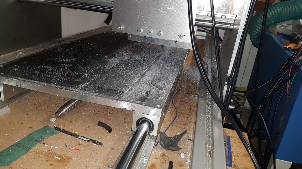
During the abortive self milling attempt I realised that the bed was not orthogonal the the Y and Z axes. To fix this I asked the machine to mill itself flat,
This was a long operation.The bed is 600 x 350mm and I needed to take about 0.8mm off in 0.2mm steps using a 6mm end mill. So a day later the bed is level and I star to drill the holes for the clamps on my vertical mill.
With all the holes cut I tapped them to fit the clamping kit I have for the mill.
These are great for fastening variable height work pieces.
With everything in place. I attempted my first milling operation.

I'm using MACH3 on a an old Windows XP machine I blagged from work with a Chinese stepper motor driver and power supply driven from the serial port. It was at this point I realised the X axis was inverted. A simple checkbox change in the MACH3 application to sort it out.

Friday, 8 September 2017

More CNC router


Visit Tagbits to see the full range of tagger products described in this blog.

I have been continuing work on my DIY CNC router this week by starting on the Y axis. This moves along the linear rails at the top and bottom of the Y gantry:


The Y axis needs mounts top and bottom for the linear bearings, shown here in blue.


I bought some 15mm aluminium plate from Materials4me.co.uk cut to size. I was quite impressed with their price and service as the pieces arrived cut accurately. I used the print and punch technique I described here to ensure the holes I needed were accurately aligned with the holes in the bearings.


The holes aligned perfectly but, as I had simply stuck a 2D print of the centres onto the plate and then drilled, I had failed to align the holes with the edge of the plate. This is how it should be:


And this is what I ended up with:


I realised that I would be unable to accurately align the paper with the centres printed on it with the edge of the work piece. Which brought me to a complete halt. A few months ago I was fortunate to take possession of a Warco WM-16 vertical milling machine.


I fitted it with a third party digital read out for the X and Y axes. This uses optical sensors to allow me to position the bed to an accuracy of 0.005mm. By aligning the work piece parallel to the bed, and centring the mill on one of the corners I can accurately drill all the holes knowing that they will be aligned with the edge.


The only issue is to accurately place the work piece. To do this I clamped the piece to the bed. I then used a dial indicator to check the part alignment by winding the bed backwards and forwards. Noting the change from one end to the other and moving the piece to compensate until the dial did not move (by much) from one end to the other it is possible to get the piece edge parallel to the bed axis.

Using an edge finder I was able to align the chuck with the corner of the piece.

Here is how they work:

And with a print out annotated with dimensions from the CAD system, using the digital read out I was able to drill each hole with fantastic accuracy.


Here is the Y axis half assembled.


In conclusion, the print and punch method I have used previously is great for aligning holes unless their position needs to be relative to some other edge.

Wednesday, 7 June 2017

Casting PCBs in acrylic


Visit Tagbits to see the full range of tagger products described in this blog.

I've been trying to optimise the way I make Milestag sensor domes. Previously I have thermo formed acrylic sheet but this is very labour intensive. The acrylic sheet needs to be cut to size, heated in the oven, force formed, cut and sanded.

In an attempt to reduce effort, I investigated using acrylic resin to encapsulate the sensor PCBs. Initially I tried dental alginate as a moulding agent. Using the formers my neighbour made (see link) I made some moulds. These appeared to be OK until I tried casting acrylic resin into them. The alginate when set and flexible has too high a water content and this interferes with the resin curing process. Simply leaving the alginate mould longer to dry makes it become hard and dimensionally unusable.

I then tried silicone mould making kit from amazon. First I laser cut a box using Makercase that was large enough to hold the formers.


I glued this together with a hot melt glue gun. This ensures the moulding material does not leak out when it is poured.


The silicone kit comes with a white base and a pink hardener. This makes it easy to ensure it is mixed correctly. I use the larger part of a Muller corner yoghurt to mix in as the triangular shape makes an excellent pourer.


Initially I poured a 5mm layer of silicone into the box. This forms the bottom layer of the mould.


I then placed two formers onto this layer, and filled with silicone.


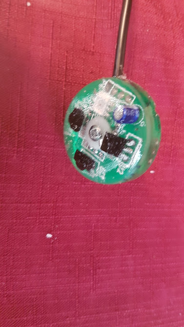
After the silicone had cured (about 12 hours) the box was broken away. I cut the mould in two and 3D printed a mounting jig to hold the sensor PCBs in place. I also drilled a hole in the side of the mould to allow the sensor cable to exit. This was smaller than the actual cable to prevent the resin from leaking.

After pouring in the acrylic resin I left it to cure for 12 hours.
The parts are easily removed from the flexible silicone mould. The acrylic seems to not fully cure at the interface to the mould, leaving a cloudy finish. However, a few tens of minutes exposed to the air and it clears nicely.