My youngest is 11, and I decided to make him an electric scooter. I sent off for a hub motor kit from AliExpress and a 42V 8Ah LiPo battery:

I also ordered a cheap (£20, ~$25) adult kick scooter from ebay. The plan was to make a self contained battery/hub motor/controller unit that simply bolted onto whatever I chose.

Someone had conveniently modelled the hub motor on GrabCad. So importing this into my CAD package really speeded things up. I designed this unit which comprises of the motor mount and a base plate which is what I'll use to fasten the assembly to the target.


On checking my first attempt I realised that I needed to minimise the angle the brake cable was at. Obviously it is best to minimise the angle it has to bend through.

So with an updated design, I used my CNC router with a 1/8" single flute bit to cut the arms. I manually brush cutting fluid on every other layer to prevent the aluminium gumming up the cutter. It's a self designed router using nema 23 4Nm steppers with 20mm ballscrews so it's well capable of cutting ally.

With the arms cut, I realised I'd need to prevent them from shearing, so I made a bracing piece to prevent this.


With the motor arms made, I needed to create some holes to accept M6 bolts which mount the arms to the base plate. My 2.5D router is incapable of creating these, so I used my Warco WM16 mill with DRO to align, drill and tap the holes as required:


As the holes get closer to the arm hub shaft mount, I was unable to use a standard tap wrench as it's handle fouled the arm.I used a ratchet tap wrench I got from BangGood to finish off the last hole.

With the motor assembly completed, it was time to fasten it to the scooter..

I printed at 1:1 ratio the hole centres for the base plate, and spray mount glued this the rear of the scooter, after cutting off the rear wheel.

Using an optical centre punch I accurately marked the centres for each bolt.This really is the best way to centre your holes from a 2D drawing, and they cost less than £30.


A spotting drill ( with a cutting angle of 90 degrees) helps to ensure the centres are exactly where they need to be before drilling to the correct size.
Impatiently I taped the battery to the rear of the scooter, wired up the motor controller and, being risk averse (to myself), persuaded my youngest to test it....

This test was premature. After about an hour I got 'Dad, there are sparks". "Rubbish" says I...until I see them for myself. The edges of the aluminium arms had worn into the Lipo battery as it bounced up and down on my shitty tape mounting. eventually wore through the (thin) outer skin of the battery and started shorting the cells. A brief moment of blind panic resulted in a battery removal and a note to create a more robust mount.
I laser cut a battery box from 6mm acrylic. This was to be mounted on a aluminium plate bent and fastened to the motor mount.


The brushless hub motor controller came as part of the kit. This is mounted underneath the battery plate.

I also decided to encase the acrylic battery box in an aluminium sheath. I used my ancient metal folding machine to create a top hat profile to go over the top of the battery box.


With this all in place, I was voted best Dad ever....
Until the shitty scooter I bought snapped in half:

This is when the modular approach shone! I went to the local sports branch Decathalon (The scooter/skateboard/rollerblade isle is very similar to the 1975 movie Rollerball...with kids on every available device zooming up and down the aisle, plus abandoned skateboards as physical traps...) I got another adult scooter at 3x the original price. I promptly cut off the rear wheel (no thanks, I don't want your extended warranty) and simply repeated the print, punch drill method to replant the motor assembly. Due to the moulding of the new scooter, I had the cut away some more of the rear of the scooter to allow for the cap head bolts I used to connect the motor arms to the base plate.


With this all in place, I had a reliable scooter that so far, had stayed in one piece. Now it was time to start the improvements. My son's major complaint was the vibration through the scooter. The rear wheel hub motor has a solid rubber tyre....not much I could do there. But the front wheel was a solid silicon..ish thing.

Adult scooters seem to use 200mm (8") wheels as standard to I ordered a pneumatic replacement from Amazon.

Trouble was, when this arrived its hub shaft was 10mm, but the scooter I had was 8mm. The original wheel had a 8mm diameter bolt which I really wanted to keep.

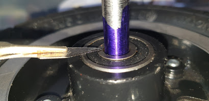
I decided to make a 10mm shaft for the new wheel that would mount around the 8mm diameter (original) bolt. I used my lathe to drill a 8mm hole through a 10mm bar I got from ebay,

The shaft was cut to the appropriate length by coating it in engineers blue.

Placing the shaft in the new wheel, I used a scalpel to mark the height of the new wheel hub.
This gave me an exact mark to cut the sheath on the lathe.

With the new front wheel in place, the ride is much smoother. Son #2 is happy and practising wheelie (yes... he really should have had a helmet on here. I routinely insist upon it...but this one time I forgot.....I am a bad dad).....
With this modular motor unit, I'm wondering what else I could bolt it to.Maybe something for HackyRaces at EMF camp 2020?....
No comments:
Post a Comment